Saturday, February 28, 2015

All About Scopes - VIII

In our last post, we looked at how manufacturers make their scopes waterproof, fog-proof, durable etc. In today's post, we will look at the subject of parallax errors, as it pertains to scopes.

Parallax is the optical illusion that causes objects to appear aligned if they're not in the same plane, when viewed from a different angle. Well, that's the textbook definition, but what does that really mean? Assume you're sitting in the passenger seat of a car and your friend is driving. If you look at the speedometer, it may appear to you that he is driving at, say, 75 mph, when he's really driving at 70 mph. This is because you are viewing the speedometer from an angle and since the speedometer needle is at a different plane than the dial behind it, you think the speedometer is showing a different speed than your friend, who is sitting in the driver's seat. This optical illusion is called the parallax effect.

So now that we know what parallax is, how does it apply to scopes? Assume a simple scope with only two lenses, an objective lens and an ocular lens, and a reticle in between (yes, real scopes have more than two lenses, but let us imagine the simplest case for the purposes of this discussion). If the reticle is not placed at the focal plane of both lenses in the scope (i.e.) if the focal length of either of these two lenses is not exactly the same distance as the distance from the lens surface to the reticle, then parallax error happens. Due to this focusing error, moving the eye behind the eyepiece causes the reticle to appear to point to different parts of the target. Therefore, this makes aiming dependent on where the user places his head, which may cause the user to miss smaller targets, because he thinks he's aiming at the target while he's really aiming to one side of it. The focal plane moves depending on the distance to the target, so if the scope does not show any parallax error for a target at one particular distance, it will show parallax error when viewing another target at a different distance.

For scopes with 4x magnification or lower, the effect of parallax error is not that significant. For higher magnification power scopes or variable power scopes, the effects are bit more significant. The problem is that the focal plane moves as the distance to the target changes. So, there are a few ways to handle this:

  1. The simplest way is to adjust the scope at the factory, so that it is parallax corrected for the range that it is most expected to be used. This range is called the zero-parallax range. For most hunting scopes, this is typically somewhere between 100 and 150 yards and some military scopes are parallax corrected at 300 meter ranges. This is the approach used by most scope manufacturers. For targets at ranges outside what the scope is adjusted for, there will be some parallax error. However, in many cases (e.g. high powered hunting rifles), the error at ranges outside the zero-parallax range is acceptable, because the target on the other end is relatively large.
  2. The second method is to make the objective lens of the telescopic sight be adjustable, so that the focal plane can be moved to compensate for a target at a different distance. Such scopes are called AO or A/O models, with the letters AO standing for Adjustable Objective.
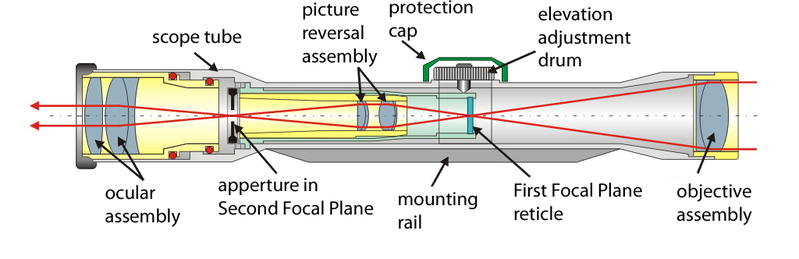
  3. The third method is the most complicated, but it involves making an internal lens in front of the reticle adjustable, to move the focal plane back and forth to compensate for parallax errors. Naturally, there has to be some gear mechanism to adjust the position of the internal lens. Typically scopes will have an extra parallax knob on one side and turning this knob operates the mechanism that moves the internal lens around.

So how does a person check if a scope is parallax corrected properly at a given range? The procedure is simple:

  1. First the person aims the scope at a target at a known range.
  2. Next, the person secures the rifle so that it cannot move.
  3. After that, the person views the target through the scope and moves his head around, without touching the rifle.
  4. If the reticle's cross-hairs appear to move to different parts of the target when the user's head is moved, the scope is not parallax compensated at that range. If the cross-hairs stay pointing to the same place on the target, this means the scope is parallax compensated correctly at that range.
In our next post, we will study mounting accessories for scopes.

Thursday, February 26, 2015

All About Scopes - VII

In our last post, we looked at lenses used in a scope, as well as lens coatings. In today's post, we will study some more details about modern scopes.

One of the requirements of a good scope is that it must be usable in all weather conditions. In the early days of telescopic sights, moisture and dust particles would enter the body of the scope and deposit on the lenses from the inside, which causes distortion of the image. Many modern scopes are now made weatherproof or waterproof. There is a difference between the two terms: weatherproof scopes can withstand a bit of light rain, but cannot really be immersed in water, whereas waterproof scopes can generally be immersed completely in water for a little while and still work. Fully waterproof scopes are completely sealed using multiple neoprene rubber O-ring seals around the external facing lenses and the control knobs. This ensures that not only water is kept out, but so are dust particles and small debris as well.

Back in the early 1940s, one of the major problems of scopes was that the lenses would fog up, when exposed to rapid temperature changes, especially in humid areas. The fog or mist would settle on the lenses and make the scope unusable. This is one of the reasons that legendary Finnish sniper, Simo Häyhä, used his iron sights instead of his telescopic sight, during the Winter war between Finland and Russia. A scope can be affected by fog, even if it is completely sealed. This is because the air inside the scope may contain water vapor and oxygen, while it is is being sealed in the factory. The solution to this issue was first invented by Leupold in 1947. The story goes that Marcus Leupold, son of the company founder, Fred Leupold, was an avid hunter, and one day while deer hunting, he missed a big  Oregon Blacktail buck because his scope fogged up. He came back out of the woods swearing, "Hell, I can build a better scope than this!". Leupold's solution was to replace the air inside the barrel tube with a gas that has no moisture content and therefore, cannot form condensation on the lenses. The first fog-proof scopes made by Leupold were filled with nitrogen gas. These days, fog-proof scopes are usually filled with nitrogen, argon or a mixture of argon and krypton gases. The scopes are hermetically sealed to prevent the gases from leaking out. It must be noted that just because a scope is waterproof, doesn't imply that it is fog-proof, because the scope may have been completely sealed to make it watertight, but the air inside it could still contain water vapor. On the other hand, if a scope is fog-proof, it implies that it is waterproof as well, and the air inside it has been purged out and replaced with a dry gas containing no water vapor, before it was sealed. Quality scope manufacturers will often advertise that their scopes are "nitrogen purged", "argon purged" etc. What this means is that the air inside the scope has been replaced by nitrogen or argon.

One more thing to note about fog-proof scopes is that only the interior lenses in the sealed scope body will not fog up. It is still possible for condensation to form on the surfaces of the two outside lenses, because these are exposed to the atmosphere.

It must be noted that before good seals were invented for scopes, mold and fungus could also form on the inside lenses of a scope. Now, with the scopes being hermetically sealed and filled with a gas that does not support life, this does not happen any more.

View from a Romanian-made PSO-1 scope, originally invented by the Soviet Union

The above image shows the view from a Romanian PSO-1 scope, which was originally designed by the Soviet military for the SVD rifle. The PSO-1 is completely sealed and filled with nitrogen gas to prevent fogging, and it can reliably function with temperature ranges of -50 C to 50 C (-58 F to 122 F)

The outside of the scope body also needs to be tough, but light. Back in the day, when the first scopes were developed in the 1830s and 1840s, they used to be made out of brass, due to its resistance to corrosion. In 1855, William Malcolm opened a factory to make rifle scopes in Syracuse, New York. His scopes were among the first to use a seamless steel tube for the body of the scope. While steel is a much more durable material than brass, it is also much heavier. During the 1940s, due to inventions made by the aviation industry, aluminum alloys were developed and the prices of aluminum dropped as well. Many modern scopes today have bodies made of aluminum alloy. An aluminum body is also pretty durable, but it is much lighter than steel. In order to resist corrosion, most aluminum bodies are anodized or hard anodized. High quality scope manufacturers use 6000 series grade of aluminum, which are generally referred to as "aircraft aluminum alloys", because these are heavily used by the aviation industry. Examples of these aluminum alloy grades are 6061-T6 and 6061-T651, and if a high end manufacturer is using these, they will let you know in the advertising, because these grades of alloy are much more expensive than ordinary aluminum alloys.

In our next article, we will discuss parallax error and how to work around it.

Wednesday, February 25, 2015

All About Scopes - VI

In our last post, we started looking into what is inside a scope. In today's post, we will look more into the subject of lenses, as used in scopes.

Lenses can be made of different materials. Cheap scopes might use lenses made of plastic, whereas better quality scopes have glass lenses. Really high quality scopes use correspondingly high quality glass for their lenses. We will look into what all this really means.

During physics classes in school, the reader might have seen diagrams about lenses similar to the one shown below:

Image licensed under the GNU Free Documentation License Version 1.2

We saw this image in our previous post. It shows that light coming from a great distance is focused by our lens, onto a point and the distance between the center of the lens and this focal point is called the focal length (shown by 'f' in the image above). Well, this is all very good in theory, but in actual practice, some of the incoming light is reflected back, instead of passing through the lens. This happens even on lenses made of glass. Anyone can verify this fact by looking out of a plate glass window -- notice that there is a faint reflection of yourself visible through the glass, no matter how well polished it is.

The amount of light being reflected back depends on the material that the lens is made of. This reflection can be reduced by applying coatings on the lens (we will study these in a few minutes.) Typically, each air-to-glass surface could reflect back about 3-6% of the incoming light and each lens has two such surfaces. Now, in a simple telescope, we just have two lenses and that's four surfaces. However, as we saw in the previous post, just using two lenses in a tube gives the user an inverted image. If we need our image to be facing the correct direction, we need at least two more erector lenses to flip the image back up and we may also have another flat glass plate onto which the reticle is etched. Suddenly, we are looking at upto 10 surfaces and maybe even more, if there are more lenses or glass plates inside the scope, upto 16 or 18 surfaces even. The amount of light being reflected back by all these surfaces start to add up and this means we could be losing upto 50% of the light coming into the scope, due to the reflections from the various surfaces. Therefore, in low light conditions, it could make the image much harder to see.

So where does this reflected light go? In many cases, it doesn't just disappear off into the distance. Instead, a part of the reflected light keeps bouncing from surface to surface of the various lenses inside the scope and after the second, third or fourth (or fifth, sixth etc.) reflection, some of this light eventually comes out of the eyepiece. This scattered light is what causes the so-called "lens flare", which causes the image to become hazy, reduces the contrast of the image, removes image details and shows rings of different colors around the image.

An example of lens flare. Notice how hazy the image looks.

One more thing to note is that the glass in the lens does not pass all wavelengths of light through the same way. Therefore, rays of light of one particular color may reflect more light from the glass than rays of light of a different color.

The way to reduce all these problems is by applying special anti-reflection coatings on the glass surfaces. As early as 1886, Lord Rayleigh had discovered the use of thin film coatings on lenses and in 1909, Harold Dennis Taylor had discovered a chemical process for producing such coatings for Cooke Optics Ltd (a British manufacturer of camera lenses). These coatings work because they have a refractive index value that is between the refractive index values of air and glass and they reduce the amount of light reflected back than if the light were to directly travel from air to glass. Coatings of this sort can halve the loss due to reflection.

Another type of anti-reflection coating is based upon using the principle of light interference, first discovered by Alexander Smakula, an Ukrainian-born scientist working for Carl Zeiss AG of Germany in 1935. This was a significant improvement to anti-reflective optical technologies and the invention was classified as a German military secret during World War II. After the war, Dr. Smakula moved to the United States and became a professor at MIT. Most modern lens coatings use the types of coatings that he pioneered.

The most common coating material used these days is magnesium fluoride, although aluminium oxide and titanium oxide are also used. Cheap manufacturers use the dip and bake method to apply the coating, but these coatings do not stick to the lens as well and can wipe off in a year or so. High end manufacturers use a different more expensive method involving molecular bombardment and vacuum chambers to apply a thin film on the lens surface. Applying a single layer of coating can drop the reflective light loss to about 1.5-2% (compared to 3-6% for an untreated surface).

Of course, the major shortcoming of a single-layer coat is that it works best on particular wavelengths  (colors) of light, particularly if the thickness of the coating is equal to 1/4th of the wavelength of the light. The solution is to apply multiple layers of coatings, each one geared towards reducing reflective light over a different range of wavelengths. The best multi-layered coatings can reduce the reflective light loss to around 0.2% or so per surface, which means that scopes using these coatings can let over 95% of the light through and produce a very sharp image indeed.

Besides these anti-reflective coatings, some lenses also have additional coatings applied for a couple of different purposes. Anti-scratch coatings make lenses more durable and help prevent minor scratches from happening on the lens surfaces. Some lenses also have a coating that prevents water from sticking to the glass. This is because water droplets can increase the glare and reflectivity of a glass surface. Applying a coating that repels water allows the scope to be used in rainy or foggy conditions, without affecting image quality as much.

A coated lens will show a colored hue when viewed from the side. Blue hues, purple hues, green hues, red hues and pink hues are commonly seen. The color is not the color of the coating material (which is colorless), but is the color of the wavelength of light that the coating is least effective against (which is why it is being reflected back instead of being let through).

Of course, adding additional coatings also increase the price of the scope. The industry uses a few terms to describe how many coatings are applied. We will look at some of these terms now.

If the manufacturer says that their scope has "coated lenses", this means that the lenses have a single layer of anti-reflection coating applied. Usually, this coating is not applied to all the lenses in the scope either, but only to the first and last lens (i.e.) only the lenses that you can see from outside the scope. Some really cheap manufacturers only coat the outer surfaces of the two outside lenses and leave the rest uncoated.

If the manufacturer says that their scope has "fully coated lenses", this means that all the lenses  in the scope have at least one layer of anti-reflection coating applied to every surface. This offers a significant improvement over the scopes described in the previous paragraph.

If the manufacturer says that their scope has "multi-coated lenses", this means that at least some of the surfaces have multiple layers of anti-reflection coatings. This does not mean that all the lenses have multi-layer coatings applied though. Quite often, the multiple layers are only applied to the outer surfaces of the first and last lenses only (i.e.) the two lens surfaces that can be seen from the outside of the scope. The first multi-coated lenses were available commercially some time in the 1970s.

Finally, we have the scopes that are "fully multi-coated". This means that all the lenses in the scope have multiple layers of anti-reflection coating applied to all their surfaces. These are usually the most expensive types of scopes.

In general, fully coated lenses and fully multi-coated lenses produce better images than the other types.

Besides these coatings, the scopes may use additional coats. Some manufacturers apply a hard protective coating to the outside surfaces of the first and last lens, which protects the lenses from scratches and abrasions (e.g. DiamondCoat and DiamondCoat 2 by Leupold). Hydrophobic coatings break up water droplets and prevents them from sticking to the lenses. Hydrophobic coatings are available from several manufacturers, such as Leupold, Bushnell, Pentax etc. and are known by different names, such as RainCote, Rainguard, Hydroshield etc.

It must be noted that lens manufacturing technologies have significantly improved over the years. Today, it is possible to buy a cheap telescopic sight for less than $100, which has better resolution, magnification and light gathering properties than the best telescopic sight manufactured around 50 years ago. In fact, the cheap scope may not even have glass lenses, but might be using optical grade plastic lenses instead!

In our next post, we will look at some more details of the internals of scopes.

All About Scopes - V

In our last few posts, we studied telescopic sights from the outside and in our previous post, we studied one part that is inside the scope, namely, the reticle. We also talked about terms like First Focal Plane (FFP) and Second Focal Plane (SFP) in our previous post. In today's post, we will look into the parts of a telescopic sight in more detail and find out what FFP and SFP really mean.

Before we dive into a telescopic sight, let us first study lenses, in particular, a type of lens called the biconvex lens (also sometimes called a converging lens). A biconvex lens is thicker in the middle and thinner at the edges. It is typically made of a transparent material, such as glass. Since glass has a greater density than air, light bends as it passes through it (you can observe the same effect if you look into a pool of water, as objects at the bottom of the pool appear to be at a different location than where they really are, due to the light rays bending as they enter it.) In a lens of this type, when light from a great distance passes through it, the light is concentrated to a spot on the other side of the lens, called the focal point, as shown in the diagram below:

Image licensed under the GNU Free Documentation License Version 1.2

The distance between the center of the lens and the focal point is called the focal length of the lens (marked as 'f' in the figure above). Before you start yawning after reading this material, you may actually be familiar with the concept of focal length, but not realize it. As children, many of us have used a magnifying glass to burn holes into a sheet of paper (admit it, you did it too). The trick is to move the lens up and down to adjust the focus, until a tiny concentrated image of the sun appears on the sheet of paper. When the paper starts to burn, the distance between the lens and the sheet of paper is the focal length of the lens.

Now let us consider an object as viewed through a lens, as shown in the image below:

Image licensed under the GNU Free Documentation License Version 1.2

When the object is at a distance S1, at a great distance from the lens, an image can be projected onto a screen at a distance S2 on the other side of the lens (where S2 is much smaller than S1). We will not study the cases where the object is located at a closer distance to the lens (e,g. if it is closer than the focal length or twice the focal length), as these are irrelevant to our object of study.

The main thing to notice in the above diagram is that the image is upside down because of the way that the lens bends the light reflecting from the object. As you can imagine, this is not very useful for telescopic sights because people aren't used to seeing things upside-down. We will study how this is rectified later.

Now that we've studied how light passes through a single lens, let us study how light passes through two lenses (i.e.) a simple refracting telescope similar to one used by Galileo in the 17th century,

Click on the image to enlarge

The above image shows how light passes through two lenses. The lens on the left is the larger objective lens, which has a longer focal length, and the lens on the right is the eyepiece lens (otherwise called the ocular lens). We encountered these terms a few posts ago, when we studied the external parts of a scope.

As you can see from the images above, the two lenses collect more light than a human eye can by itself, and give the user a brighter magnified image. Note that because of the way that the light bends, the image that the user sees is upside-down. The fact that the image appears upside-down doesn't matter when viewing symmetrical objects such as stars, the planets, the moon etc. However, it does definitely matter when viewing targets on the earth, as users prefer to see their targets aligned in the proper direction.

Therefore, scopes work around this issue by having another set of lenses in between the objective lens and the ocular lens. These intermediate lenses also flip the image, therefore when it comes out of the ocular lens, the double inversion causes the image to be turned back to the correct direction, the way that most users like to see it. The image below shows how this works:

Internals of a telescopic sight. Click on the image to enlarge.

Light passes through the objective lens and the image is inverted, as we have already seen a few paragraphs above. It then passes through another set of lenses, labelled as the picture reversal assembly (also called "erector lenses") in the image above. These lenses serve to invert the image again, which means by the time it passes through the ocular lens, the image is flipped back to the correct direction. In variable power scopes, there is a mechanism to allow the erector lenses to be moved back and forth, which changes the magnification power of the scope.

Also note that the first focal plane (FFP) reticle is located at the focal length of the objective lens. There is also a second focal plane (SFP), which is located at the focal length of the erector lenses that comprise the picture reversal assembly. The reticle can be placed at either the FFP point or the SFP point. We studied the implications of placing the reticle at FFP vs. SFP a couple of posts ago and also in our last post.

We will study more about the internal parts of a scope in the next post.

Wednesday, February 4, 2015

All About Scopes - IV

In our last post, we studied some details about the reticle inside a scope. In today's post, we will look into some more uses of reticles, namely rangefinding. We had actually dealt with this topic some time ago, when we talked about telescopic sights.

The key to rangefinding in most scopes is to compare an object of known height or width against a series of markings on the reticle, to determine how far away it is. We will see how this works with a few examples.

Reticle from a Russian PSO-1 Scope, as used by the SVD rifle. Click on the image to enlarge. Public domain image.

The above image shows the reticle from a PSO-1 scope, which was originally designed for use by the Soviet military Dragunov SVD sniper rifle. When this was originally introduced in 1964, it was the most advanced mass-produced scope available. This scope is a fixed power scope with 4x magnification. It has several markings on it. The top chevron (^) mark is used as the main aiming mark. The horizontal marks (10...10) are used for adjusting for windage and also allow to lead the target, in case it happens to be moving. The horizontal marks can also be used for rangefinding, if the width of the target is known beforehand. Each marking on the horizontal 10..10 marking is spaced at one milliradian interval, therefore the calculation for finding distance can be determined by the following formula:

D = S / mils * 1000

where
D = distance to target in meters
S = Known height or width of target in meters
mils = Number of markings wide that it appears when viewed through the scope

Say the user is viewing a Land Rover vehicle, which is known to measure about 4 meters long (i.e. 13.12 feet long). Let's say that when it is viewed through the scope, it measures up to 8 markings long. Then, we put S = 4, mils = 8 in the above formula and calculate D = 4/8 * 1000, which works out to 500 meters. Therefore, the Land Rover is approximately 500 meters away from the scope.

Also notice the curved line on the lower left quadrant with the numbers (10..2). This can also be used to measure distance to the target, in this case using a human for range finding. The markings assume that an average human is 1.7 meters (5 feet 8 inches) tall. The user simply aligns the scope so that the person's feet touch the bottom horizontal line and see which marking the person's head touches, as shown in the image below:

Public domain image

In this case, the person's head touches the 4 mark, which means that the person is about 400 meters away. Using this set of markings, the user can determine ranges from 200 to 1000 meters.

The PSO-1 scope has a bullet drop compensator (BDC) to adjust range in 50 meter increments from 100 meter to 1000 meter ranges. Therefore, once the range to the target is determined, the user can turn the knob and adjust the elevation to correspond to the appropriate range and then align the target with the top chevron mark (^).

Notice that the scope also has other chevron marks (^) below the first one. These are used to shoot at ranges beyond 1000 meters. The user sets the elevation to the maximum of 1000 meters, then uses the other chevrons to line up to 1100, 1200 and 1300 meters respectively.

Now we'll look at another reticle.

Reticle used by Schmidt and Bender scope. Public domain image.

The above reticle is used by scopes made by Schmidt & Bender. Note that the center of the scope has several dots in the horizontal and vertical lines. These are called mil-dots and each dot corresponds to 1 milliradian. Therefore, if the width or height of an object is known, the user can determine the range by counting the number of dots that it covers and then using the same distance formula that we saw above for the PSO scope. Therefore, if an average person, who is about 1.7 meters tall (or 5 feet 8 inches tall), covers 4 dots when viewed in the scope, we can take S = 1.7, mils = 4 and plug it into the formula D = 1.7/4 * 1000, which works out to 425 meters.

There is also another way to quickly compute the range with this reticle, without doing any arithmetic. Note that the bottom of the reticle, there is a long horizontal line and above it are a series of smaller horizontal lines in a step pattern. These lines can be used to quickly estimate the distance to a target, using a human as the scale. To estimate distances between 100 and 250 meters, the user simply frames the target's head between the lines as shown below:

Public domain image.

The average human head is around 0.25 meters high. The two lines that best frame the top of the helmet to the chin tell the distance to the target.

For longer ranges, the same horizontal lines can be used, except that the user frames the top of the target's head to the belt buckle between the two lines.

Public domain image

Using this, the user can measure distances between 400 and 1000 meters.

Note that in both these instances, the scopes are fixed power models. Therefore the user cannot adjust the magnification power and the rangefinding calculation is easier.

For scopes with variable power magnification, the method of rangefinding depends on whether the reticle is placed on the first focal plane (FFP) or second focal plane (SFP).

Recall in our last post, we mentioned that if the reticle is placed on the first focal plane, the size of the reticle resizes with the magnification, so if the user zooms into the target, the reticle also appears to enlarge in size correspondingly. So, if a target measures 4 mil dots at 3x zoom, it will still measure 4 mil dots at 10x zoom, when using a FFP reticle. Therefore, for a variable power scope using a FFP reticle, the range calculation formula is the same as that of the fixed power scope, D = S/mils * 1000.

We also mentioned in our last post, that in a reticle placed at SFP, the size of the reticle does not change with magnification power. Therefore, for a SFP scope, the mil-dot range estimation is calibrated accurately only at one particular magnification power, generally at the highest magnification power setting, or sometimes at the middle magnification power setting. Some SFP scopes have an index mark on the power ring, to show at which magnification power setting the mil dots are accurate (for instance, some manufacturers set it at 10x power, Bushnell generally sets theirs at 12x power). The formula for range estimation changes a bit in this case. Assume a SFP scope where the mil-dots are calibrated accurately at 10x magnification power. The distance formula for this scope is:

D = (S/mils) * (mag/10) * 1000
where
D = Distance to the target in meters
S = Width or height of the target in meters
mils = Number of markings covered by the target
mag = Magnification power of the scope.

As you can see, with a SFP scope, the range calculation is a bit harder to do because it depends on the magnification power setting on the scope. Therefore, some users usually set their scope at the power setting that it is calibrated at and leave it there, so that they don't have to do the extra math. For instance, in the above example, if the magnification power is set to 10x (i.e. the same magnification power that it was calibrated at), the formula simplifies to D = S/mils * 1000 (i.e.) the same formula as for a fixed power scope. Alternatively, if they change the magnification power, they change it to half or double of the calibration setting. For example, a Bushnell Elite 4200 6-24x40 variable power scope is calibrated at 12x magnification power, so if the user wants to change the magnification power, they usually select 6x or 24x, so that the range calculation can be modified by dividing or multiplying by 2. If the user chooses any other magnification power settings, the math becomes correspondingly harder.

This is why many military scopes use fixed power scopes, to reduce the amount of math calculations that the user has to do, and also avoid the chance that the user makes an incorrect calculation due to not paying attention to the magnification power setting of the scope.