Showing posts with label Steel Barrels. Show all posts

Sunday, December 14, 2014

Forging Rifle Barrel Blanks in the 1920s - II

In our last post, we studied some parts of a factory designed to produce rifle barrel blanks. In today's post, we will continue studying the process. As noted before, some of the details come from a book, "The Working of Steel" by Fred Colvin and K.A. Juthe, and in addition, K.A. Juthe was the designer of the factory as well.

Where we last left off, the barrel blanks were straightened out and tested for straightness. The next process was to heat treat the barrel blanks and increase their hardness. We will discuss this heat treating process shortly.

The last process was to grind the ends of each blank and then grind a spot on the enlarged end of each blank and test the hardness of the blank on a Brinell machine, to ensure that the blanks met the required hardness nunbers

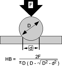
The Brinell hardness test was invented by Swedish engineer Johan Brinell in 1900. It was one of the first standardized hardness tests used in engineering and is still used today. The test is very simple. It uses a steel or tungsten carbide ball of diameter 10 mm. (0.39 inches), which is used as an indenter. The ball is placed on the surface of the object to be tested and a 3000 kg. (or 6600 lbf.) test force is applied to the ball for a specific time (normally 10 to 15 seconds). After this, the ball is removed and it leaves a round indentation on the surface of the object. The diameter of this indentation is measured and the Brinell Hardness Number (BHN) is calculated, based upon the diameter of the ball, diameter of the indentation and the force applied to the ball. For softer materials, such as aluminum, a smaller test force (e.g. 500 kg. (or 1100 lbf.) is used instead.


The above image shows a line drawing of the concept and the formula actually used to calculate the Brinell Hardness Number (HB in the image above).

Returning back to our study of the factory process, the barrel blanks were tested for hardness to make sure that they had a Brinell Hardness Number (BHN) of at least 240.


At this point, the barrel blanks were shipped off to a barrel manufacturer, who would then drill, ream, finish-turn and rifle the blanks into complete barrels.

Now. all through the description of the process so far, we've been talking about heating the blanks for various purposes. We will cover the heat treatments in detail here. There were actually four separate heat treatments done to the blanks.

  1. Heating and soaking the steel above the critical temperature and quenching it in oil, to harden the steel through to the center of the blanks.
  2. Reheating the steel for drawing of temper  for the purpose of meeting the physical specifications of the blank
  3. Reheating the blanks to meet the machineability test for production purposes
  4. Reheating to straighten out the blanks when hot.
We will study each of the four heating processes in detail. 

For the first heating process, the blanks were slowly brought up to the required heat, which is about 150 degrees Fahrenheit (65.5 degrees centigrade) above the critical temperature of the steel. The blanks were then soaked at a high heat for about one hour before quenching in oil. The purpose of this treatment was to eliminate any strains already existing in the bars that may have been put there from milling operations done to the bars. Remember that steel is an elastic substance and working it puts stress on the bars. For instance, during the production of steel, the manufacturer rolls the bars through various rollers to make them the required diameter, which causes the bars to come out stressed. The heat treatment process removed the stress caused by rolling, hammering, cutting etc. It also ensured that the heat treatment applied to the entire cross-section of the bar and not just the surface. In addition, if a blank had seams or slight flaws, these opened up drastically during the quenching process and made it easy to determine if a blank was defective or not.

The oil used for quenching was kept at a temperature of  around 100 degrees fahrenheit (38 degrees centigrade). This is an ideal temperature is to prevent shock to the steel when it is dropped into the quenching oil, otherwise it could develop surface cracks on the piece.

The second heating process (the one for drawing the temper of the steel) was a very critical operation and had to be done carefully. The steel had to be kept heated within 10 degrees of temperature fluctuation in the process. The degree of heat necessary for this operation depended entirely on analyzing the steel. Even if the steel was purchased from the same manufacturer, there was always some variation in different batches received from the manufacturer.

The third heating process (reheating for machineability) was done at a temperature of around 100 degrees Fahrenheit (38 degrees centigrade) less than the drawing temperature used for the second heating process. However, the time of soaking was almost double that of the second process.

For both the second and third heating process, after the heating was done. the blanks were buried in lime so that they would be out of contact with air, until their temperature had dropped down to room temperature.

The fourth heating process was used when straightening the blanks. In this process, the blanks were first heated to about 900-1000 degrees Fahrenheit (482-538 degrees centigrade) in an automatic furnace for 2 hours before straightening them. The purpose of heating before the straightening was to prevent any stresses being put into the blanks during the straightening operation. This is necessary because when later processes such as drilling, turning and rifling are done to the blanks, they have a tendency to spring back into the shape they were in when they left the quenching bath. By heating before straightening, the blanks are prevented from doing this.

Another method was later found to produce an even better barrel blank. The blanks were first rough-turned to the final barrel diameter and then heated to about 1000 degrees Fahrenheit (538 degrees centigrade) for about 4 hours before sending them to the barrel manufacturer. Blanks produced with this method remained practically straight during the different barrel making operations (drilling, reaming, finish-turning and rifling). This meant that the barrel manufacturers didn't need to straighten barrels after they were finished (which was a much more expensive operation). This method was tested out with one of the largest barrel manufacturers in the US and it proved to be very effective.

As the reader might be wondering, all this heat-treating needed a large amount of oil for cooling and one of the problems was how to keep all this oil at the proper temperature. After much study, a cooling system was developed for the factory. The next two images show the cooling system as seen on the roof from the outside of the factory.


Click on the images to enlarge. Public domain images.


The next image shows the details of the cooling system:


The hot oil is pumped up from the quenching tanks through the pipe A into the tank B, From here, the oil runs down onto the separators C, which break the oil up into fine particles, that are blown upwards by the fans D. The spray of oil particles is blown up into the cooling tower E, which contains banks of cooling pipes and baffles F. Cold water is pumped through the inside of the pipes. The spray of oil particles collects on the outside of the cold pipes and forms larger drops, which fall downwards onto the curved plates G and then run back to the oil-storage tank below ground. The water pumped through the cooling pipes comes from 10 natural artesian wells at a rate of 60 gallons per minute and this serves to cool about 90 gallons of oil per minute, lowering it from a temperature of about 130-140 degrees Fahrenheit to about 100 degrees Fahrenheit. The water comes out of the wells at an average temperature of 52 degrees Fahrenheit. The pump is driven by a 7.5 HP motor and the speed can be varied to suit the amount of oil to be cooled. The plant was designed to handle up to 300 gallons of oil per minute.

The finished blanks from this factory were sent to different barrel manufacturers to drill, ream, rifle etc. to their requirements.


Tuesday, December 9, 2014

Forging Rifle Barrel Blanks in the 1920s - I

After all the stuff we studied about metallurgy in the last several posts, we will look at an ancillary subject today, forging of rifle barrel blanks. We have already covered barrel manufacture from barrel blanks in some detail in previous posts many months ago. In today's post, we will study the process of manufacturing the barrel blanks as it was done in a factory in America in the 1920s. In particular, this was a factory belonging to Wheelock, Lovejoy & Company, which was designed to mass-produce rifle barrels designed to meet specifications demanded by some foreign governments. Some of the pictures and information in this post was taken from the book "The Working of Steel" by Fred Colvin and K.A. Juthe, and in addition, K.A. Juthe was the designer of the factory as well.

This factory did not manufacture its own steel: instead, they bought what they needed from a large steel manufacturer. The steel manufacturer made the steel to the required specifications and supplied them in the form of bar stock, but the length of the supplied bars was longer, typically each bar measured something like 30 or 35 feet long (about 9.1 to 10.7 meters long).

Cutting the bar stock to size.

Therefore, the first step in the process was to cut each steel bar into smaller lengths to make barrels. The bars came on trucks and were fed through the cutting-off shear, where they were cut into pieces of the proper length. The pieces were actually a little longer than the final barrel lengths, to allow for trimming during the machining process.

A close up of the details of the cutting off is shown in the next image.


A is the stock stop bolted to the side of the frame and the ledge formed by the strip bolted to the stop, keeps the bar stock level during the cutting process. The hold-down B prevents the back end of the steel bar from flying up when the bar is cut. The knife C has several notched edges with which the barrels can be cut, so that it need not be taken out for resharpening, until all the notches are dull.

The cut barrel pieces then passed into the next room, where there was a forging or upsetting press.

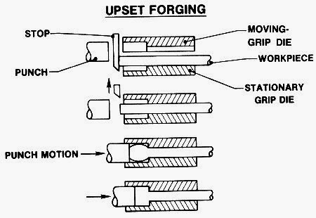
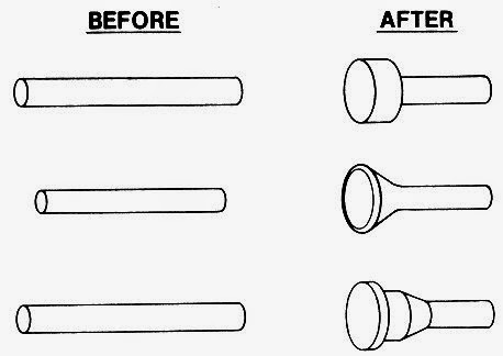
Upsetting (or more properly, upset forging) is a process of increasing the diameter of the end of a work piece, by compressing it along its length inside a die. The images below show the process.


The barrel pieces were heated in a furnace to soften them, before being sent through the upsetting press. The press could handle the barrels from all the heating furnaces shown in the room. The men changed work at frequent intervals, to avoid excessive fatigue.

The barrels were then sent through a continuous heating furnace to be reheated and then straightened out as much as possible before being tested for straightness.

A Continuous Heating Furnace


In the above machine, each barrel was tested for straightness by placing it on the rollers as shown in the image above. The screw on the press was used to apply pressure and straighten out the barrel as needed.

We will continue our study of the process in the next post or two.

Monday, November 17, 2014

Metals Used in Firearms - XV

In our last post, we studied how the Bessemer process made it possible for the first time for steel to become as cheap or cheaper than cast iron. The quality of steel wasn't as high as the crucible process, but the price of steel was now much more affordable, which meant there were more manufacturers offering steel barrels in their firearms.

One of the problems with manufacturing steel with the Bessemer process was that passing air through the molten metal sometimes formed gas bubbles and these would form internal blow holes in the steel ingot as it cooled down. Also, a steel ingot shrinks as it cools and this shrinkage could also cause gaps and hairline cracks to form in the ingot. These flaws in the ingot could weaken the final product, if not properly eliminated.

The solution to this problem was found by the famous British engineer, Sir Joseph Whitworth. We had studied about his inventions when we studied the Whitworth rifle many months ago. This innovative rifle was much more accurate than its competition, but was more expensive to manufacture, which is why it was rejected by the British military. However, it was used by other people who had need for accurate rifles, such as confederate snipers, during the US Civil War. Sir Whitworth continued to make improvements to his rifle and discovered a way to remove most of the flaws in steel ingots. His method of manufacturing steel was called fluid compressed steel, and we will study the process in today's post.

We know that Whitworth first discovered his method in 1865, because he registered a patent during that year, but it wasn't until 1869 that he finished building the machinery to manufacture the steel in quantity.

The steel is manufactured using the process we studied in our last post, but when the steel is poured out into a mold, instead of allowing it to cool by itself, a hydraulic press is used to apply pressure to the ingot while it is still in a liquid or semi solid state. This pressure causes most of the generated gas bubbles and cracks in the ingot to collapse or move towards the ends of the ingot. To give some idea of the pressures involved, an ingot measuring about 15 feet (4.57 meters) in length before compression,decreases about 12 inches (30.5 cm) in length after compression, to form a bar of length 14 feet (4.27 meters). After the steel solidifies, the two ends of the ingot are cut off (about 20% of the length) and discarded and the remaining bar contains far less bubbles and cracks. This bar can now be used for various applications, such as making quality steel barrels.

A Whitworth Hydraulic Press at the Armstrong-Whitworth company. Notice the man standing on the left side of the press.
Click on the image to enlarge. Public domain image


Whitworth fluid compressed steel was generally acknowledged by many gunmakers, to be of excellent quality and Whitworth's name became a selling point. Therefore, many firearm manufacturers of that era would often stamp Whitworth's name and trademark (a sheaf of wheat) on their barrels, alongside their own names, to show that these barrels were made of superior quality steel.

A high quality LC Smith shotgun featuring Whitworth Fluid Compressed Steel barrels. Click on the image to enlarge.

Another double-barreled gun showing the Whitworth trademark (a sheaf of wheat). Click on the image to enlarge.

Whitworth Fluid Compressed Steel was used by many high end manufacturers, such as Purdey and W.W Greener in England, and Parker, Remington and LC Smith in the United States.

Whitworth's patent for fluid compressed steel expired in 1879, but a special committee of the British government extended his patent for 5 more years. After the patents finally expired in 1884, many other manufacturers started making their own versions of fluid compressed steel, The most famous competitor of Whitworth was Krupp Steel works from Essen, Germany, who made their own Krupp fluid compressed steel. Like Whitworth, many manufacturers began to advertise that they used Krupp steel in their barrels.

A pair of barrels made of Krupp Fluid Steel. Click on the image to enlarge.

Some famous American manufacturers like Lefever, Stevens and Ithaca were known to use Krupp's steel, as well as German manufacturers, such as JP Sauer & Son.

Krupp and Whitworth were the two famous manufacturers of fluid compressed steel, but there were also other manufacturers such as Jessop, Sterlingworth, Chromox etc. Fluid compressed steel continued to be used in barrels till about 1925 or so, while other ways of manufacturing steel to eliminate gas bubbles were discovered. We will study some of these other methods in a couple of posts.

In the next post, we will study the open hearth process to manufacture steel and then move on to more modern methods.

Saturday, November 8, 2014

Metals Used in Firearms - XIV

In our last post, we saw how crucible steel was manufactured after around 1740 or so, using the process invented by Benjamin Huntsman. While crucible steel was a significant improvement over blister steel in terms of quality, it was still somewhat expensive to produce. Therefore, many firearm manufacturers used steel for smaller parts, such as sear springs, frizzens etc. and many barrels were still made of wrought iron, instead of steel. As we saw in our previous post, some larger manufacturers like Remington and Colt did offer superior steel barrels after 1820 or so, but they cost over double the price of wrought iron barrels and therefore, both companies sold wrought iron barrels as well, as a cheaper alternative to their steel barrels. High end firearm manufacturers combined steel and iron to make damascus barrels. These were beautiful to look at, but they were expensive to produce and generally designed for rich clients.

So what was the reason for the higher cost of steel. Well, let's look at the processes involved to convert iron ore to steel using the crucible steel method, as done before the 1850s:

  1. Convert the iron ore to pig iron or cast iron, using a blast furnace.
  2. Convert the cast iron into wrought iron, using a finery forge, or later on, a puddling furnace.
  3. Convert the wrought iron into blister steel, using the cementation process.
  4. Convert the blister steel into crucible steel. using the Huntsman process.

All four steps needed to be done to produce crucible steel, whereas producing wrought iron only required the first two steps. Steps 2, 3 and 4 also required skilled workers with specialized training (we studied about specialized workers called puddlers, puller-outs and teemers in the last few posts). Step 2 was also not geared towards mass production. Using finery forges was a slow process and work-intensive in nature. While the puddling forge replaced the finery forge, it also required specialist workers and puddler workers generally had short life spans as well, due to the unhealthy and stressful nature of their work. Step 3 took wasn't a continuous process either and took the longest time to finish (typically, a batch would take 2 weeks to convert from wrought iron to blister steel). Step 4 was also done in batches, since it was limited by how much puller-outs and teemers could lift at a given time. Step 4 also typically took around 4 hours to finish. No wonder, crucible steel/cast steel cost so much more than wrought iron.

Improvements in the crucible steel manufacturing process, done in the United States in the middle of the 19th century, rendered step 3 unnecessary, as it was now possible to convert wrought iron to crucible steel directly in the crucible. However, the improved process still took a few hours to accomplish, was still a batch process and required skilled workers. Therefore, wrought iron was still the material of choice for many gun makers. Incidentally, large construction projects like bridges and towers of this era also generally used wrought iron, because of the non-availability of large volumes of steel to meet the demand.

The price of steel did not drop until an English engineer named Henry Bessemer invented the Bessemer process in 1856. With his invention, the cast iron produced in step 1 above could be directly converted to quality steel, without going through steps 2, 3 and 4. It could also be produced in larger volumes than using the crucible process and could be done in 30 minutes, further reducing costs. In fact, the steel produced by his method cost the same price or cheaper than wrought iron. Since steel is generally harder and tougher than wrought iron, after this low-cost production method was invented, most industries stopped using wrought iron altogether and switched to steel completely. In fact, in today's modern world, the only people producing wrought iron are traditional blacksmiths in tiny shops employing only one or two people. We will study how the Bessemer process worked in today's post.

The process consists of melting cast iron in a large vessel (called a Bessemer converter) and blowing air through the molten iron from the bottom of the vessel, through nozzles called "tuyers". The oxygen in the air oxidizes impurities such as silicon, manganese and excess carbon and forms oxides, which either escape as gases or form lighter slag which floats on top of the molten iron and can be separated. The oxidation of impurities also raises the temperature and keeps the iron in a molten state. The materials used to line the insides of the Bessemer converter vessel also play an important part in removing some impurities, as we will see below. The production of oxides causes a large flame to appear in the mouth of the vessel and monitoring this flame gives an indication of how the oxidation process is proceeding. After the oxidation is complete, the slag is removed and a precise quantity of carbon and other elements are mixed into the molten metal to form steel. This molten steel is then poured into molds to solidify.

A Bessemer converter. Click on the image to enlarge. Public domain image.


The process of converting cast iron to steel only takes about 20 to 30 minutes and doesn't use as much coke as some of the other processes we've studied in the past. Also, large vessels can be built to handle about 30 tons of metal at a time, making it more efficient for producing large volumes of steel. Typically, a factory has at least two converter vessels for efficiency, so that while one vessel is being filled or emptied, the other one is busy melting the iron.

The process of oxidizing iron (decarburizing) with forced air was actually known to people outside Europe, many centuries before the Bessemer process was invented. We know that the Chinese had a decarburizing process in the 11th century AD and there are European traveler accounts of Japanese using a similar process in the 17th century. However, they produced steel in smaller quantities only. It was Henry Bessemer, who converted this process into a large scale industrial production process and we therefore know it as the Bessemer process.

The invention of the Bessemer process was due to a lucky accident. The Crimean war had started and Henry Bessemer happened to meet King Napolean III in 1854 in Vicennes, France and had a short conversation with him, where the King said that what the world needed was for someone to invent a better and cheaper way to produce steel in quantity, so it could be used for guns (both firearms and cannon were largely made of wrought iron at this time). Henry Bessemer started working on the problem in 1855 and patented the process in 1856. A lucky discovery by him actually gave him an insight into the process. He was working with a puddling furnace and by chance, some of the wrought iron pieces ended up on the side of the puddling chamber and were exposed to the furnace's heat for a while. When he went to push those pieces back to the middle, he discovered that the pieces had been converted to steel. This gave him the idea to rework the furnace to push high pressure air via pumps through the iron. "But wait a minute", the reader asks. "Won't blowing air on top of an object cool it down? People blow air via their mouths to cool down hot coffee or hot soup, so why doesn't blowing air cool down the iron?" Well, hot coffee or hot soup don't contain impurities that burn, whereas cast iron does. The oxygen in the air causes the impurities to burn, which increases the temperature of the vessel, which in turn burns more impurities and increases the temperature of the vessel even more, until the iron melts completely. The first impurities to burn are the silicon and carbon in the pig iron, followed by the rest of the impurities.

In order to make the process more popular, Bessemer licensed his process out to four different vendors in different geographic areas, with the plan of gaining market share for his method. He sold the process to the four vendors for a total of £27,000, but none of them could make it work successfully and he ended up getting sued in court! In the end, he bought back his patent licenses for £32,000 and built his own factory. In his initial process, his method consisted of burning off just enough impurities to reduce the carbon content to the required amount to make the grade of steel desired and then stopping the flow of air. Well, that was the theory anyway, but it didn't work so well in practice and he spent large sums of money unsuccessfully trying to figure out how to determine when to stop blowing the air. Another issue was that certain impurities in the steel also react with nitrogen gas, which happens to be a large part of air as well.

It was left to another British metallurgist, Robert Mushet, to provide the solution. Before the Bessemer process was invented, Robert Mushet had discovered in 1848, that adding a small amount of spiegeleisen (an alloy that is rich in carbonates of iron and manganese mainly, with a little carbon and silicon as well) to steel made it much easier to work with when heated. The sample of spiegeleisen was brought back to him by a friend who had returned from a tour of the Rhineland area in Germany and thought that he might like to look at the shiny mineral (spiegeleisen is very shiny and the name literally means "mirror iron" in German). We now know that adding manganese to steel has the effect of increasing the malleability of steel, as we saw earlier when we first started this series.

A sample of Spiegeleisen. Click on the image to enlarge. Public domain image.

Shortly after the Bessemer process was invented, another friend, Thomas Brown, knowing of Robert Mushet's interest in metallurgical problems, brought him a sample of poor quality Bessemer steel and challenged him to improve it. His solution was very simple and was overlooked by everyone else, including Henry Bessemer. Instead of trying to determine when the level of carbon content in the steel had reached the required level and then stopping the flow of air, he instead kept pumping in more air until the entire content of carbon and other impurities had burned off. After all the carbon and impurities had been burned off, the flames would no longer shoot out of the front of the furnace thus indicating that they were all burned off, that's when he stopped the flow of air and added a precise amount of spiegeleisen back into the molten iron, to add back the required amount of carbon and manganese and form high quality steel. This improvement made it much easier to produce steel rails and bars. He also invented other processes to improve the casting of steel (his method is still used today) and also developed the first true modern tool steel. Robert Mushet dreamed that he and Bessemer would become rich men by his inventions, but he didn't manage to profit by them at all, whereas other people did. By 1866, he was bankrupt and ill and his 16 year old daughter went to London alone and angrily confronted Henry Bessemer in his private office and told him that he wouldn't have become rich without her father's invention. Henry Bessemer saw the logic in her argument and paid Mushet a pension of £300 annually (which was a big sum of money in those days) until he died in 1891.

There was also another problem with Henry Bessemer's process. Well, it really wasn't a problem for him, because he was in England and English iron was low in phosphorus content. Remember the section above, where we mentioned that the lining of the Bessemer converter vessel also plays a role in removing some impurities from cast iron. Bessemer lined his vessel with clay and it worked very well with cast iron with low phosphorus content. The process using a clay lining is called acid Bessemer. The trouble is that in the rest of Europe, their cast iron contained a larger amount of phosphorus and this impurity wasn't removed by the clay lining, which resulted in low-grade steel being produced (phosphorus weakens steel). A British chemist by the name of Sidney Gilchrist Thomas solved this problem in 1876, with the help of his cousin, Percy Gilchrist. His solution to the problem was to coat the inside of the vessel with a lining of dolomite or limestone, which removes the phosphorus impurities. This process is called the basic Bessemer process, as the lining is alkaline in nature (as opposed to the acid nature of the clay lining). It is also called the Gilchrist-Thomas process, after its inventor. The process actually generates more slag than the acid Bessemer process. As an extra bonus, the high phosphorus content of the slag meant that it could be sold to farmers as a fertilizer, thereby increasing the profit of the factory! The invention of the basic Bessemer process was very valuable to European countries like Germany and Belgium, where the iron had high phosphorus content and Thomas' name became much more well-known in those countries than in his native England! In the United States, even though more iron ore is low in phosphorus, his method still found lots of supporters here too.

The Bessemer process quickly made Sheffield a major producer of steel. In America, a team of investors went over to England in 1863, to license the technology, with a view to using it to improve shipbuilding, armor and armaments. They built their first factory in Troy, New York, in 1865, to manufacture steel rails for trains. The main American engineer involved, Alexander Holley, continued to improve the Bessemer process and built or consulted for about a dozen different steel plants between 1866 and 1877, including the first Pennsylvania Steel plant for the Pennsylvania railroad company. An early investor who saw great potential in the improvements made by Holley was Andrew Carnegie. who hired Holley to build the Edgar Thomson Steel Works in 1873, located in Pittsburgh. This was one of the largest steel plants in the country at that time and helped make the United States a world leader in steel production, overtaking Britain by 1890 or so. Manufacturing steel made Andrew Carnegie one of the richest men in America and towards the end of his life, he donated his vast fortune to various causes, including funding thousands of public libraries and some universities (he's well known for his contributions to Carnegie Mellon University, but what is not as well known is that he also donated large sums of money to the Tuskegee Institute in Alabama and the University of Birmingham in England).  The Edgar Thomson plant is still in service, now part of US Steel, and this factory currently produces about 28% of US Steel's production in America. About 900 people work in here, many of whom had fathers, grandfathers and great-grandfathers working in the same factory as well.

With the invention of the Bessemer process, not only did the time taken to produce steel from pig iron drop significantly (it was faster to produce than even wrought iron!), it was more efficient and could work with larger volumes of cast iron as well. The cost of producing good-quality steel dropped from about £60 per ton to about £7 per ton, shortly after Bessemer started his first factory. With improvements to the process made by others, the prices dropped even more. For instance, an invention by William Jones, while working in the Edgar Thomson steel plant, improved the Bessemer process to become a continuous process. flowing molten iron directly from the blast furnace to the bessemer converter. As a result of this, steel began to replace wrought iron in many applications, as it was now cheaper to produce, as well as being tougher and stronger than wrought iron. The Bessemer process started declining in England around 1895, but it continued in other places in the world for a lot longer. Germany produced most of its steel in the 1950s and 1960s using this process, and in America, the last factory using the Bessemer process closed in 1968. One of its issues was actually its speed of production -- it ran too fast! Given that the steel could be produced in under 20 minutes, this gave little time to analyze the steel and make sure that it has the alloying elements in the correct proportions and to adjust the percentages as needed. The flame produced by burning the impurities is large and spectacular and while it is burning, people cannot approach the vessel to take samples, therefore the amounts of various elements in the steel cannot be adjusted midway through the process. One of the later improved Bessemer processes (the oxygen lance process) replaced the Bessemer process in many places. The oxygen lance process blows pure oxygen instead of air, over the molten metal, to better improve oxidation. Interestingly, the oxygen lance method was actually patented by Henry Bessemer in the 19th century, but he could never build it with the available 19th century technology, because of the difficulty of obtaining large quantities of oxygen.

We will study some more improvements in steel making in the next few posts.
Tuesday, June 8, 2010

Barrel Making: Making a Modern Steel Barrel - Part II

In our previous post, we saw how what kinds of steel are chosen to make barrels and the process by which they are drilled. Now we will continue discussing the process, after the barrel has been drilled.

As we noted in our previous post, a deep hole drill bit is designed to drill a hole slightly smaller than the desired bore. For instance, if the final gun barrel is supposed to have a bore of 5.56 mm., the drill bit might drill a hole about 5.35 - 5.40 mm. in diameter. So the next operation to be done is called reaming and the process uses a reaming machine to do this.

Reaming


The picture above is a reaming tool. A reaming tool is made of either tool steel or (in more modern times) tungsten carbide. A typical reaming bit is a cylindrical tool which has a set of multiple straight or helical cutting edges which are parallel to each other on the circumference of the cylinder. A reaming tool only removes a small amount of material (typically between 0.1 and 0.2 mm. at most) and is used to perform accurate sizing of a bore's diameter and also produce a smooth finish on the inside of the barrel. The white part in the picture above is just soft tape and is present to prevent the reamer from vibrating when it is inside the barrel.


The reamer bit is put in through the barrel and then oil is pumped in, but at a lower pressure than the drilling operation we saw in the previous post. Unlike drilling, in the reaming operation, the reaming tool is rotated and the barrel is kept still. The reaming tool is rotated at speeds of 200 - 500 rpm or so and the barrel is pulled through the reaming tool at a rate of about 2 - 5 cm. per minute or so. The oil keeps the reaming tool cool and flushes out any metal filings. In the picture above, you can see the reaming tool coming out of the barrel and dirty oil coming out of the barrel as well. The oil is filtered by a series of sieves to remove the metal particles and the oil is recycled.

Reaming produces a much more smoother finish than drilling and only removes a small part of the material, hence this is a finishing up operation. Some low quality barrel manufacturers skip the reaming operation altogether and merely drill the hole to the desired bore, which saves a bit of money, but doesn't provide a dimensionally accurate hole. All quality barrel manufacturers invariably drill a hole a little smaller than the desired bore and then use a reamer to make it the exact diameter and finish the insides with a smooth finish.

Rifling

The next process after reaming is done is to add rifling to the barrel. We've already studied the various methods of rifling previously (i.e.)
We will not talk much about the rifling techniques here, since they've already been discussed. Cut rifling is generally preferred by small custom barrel makers and the last four methods are used by larger gun making companies. Note that broach rifling, button rifling, hammer forging and flow forming add additional stress to the barrel due to their methods of machining.

Stress Relieving

Because of the drilling, reaming and rifling operations, considerable stress is induced into the barrel and this needs to be stress relieved again before further operations can happen. If you remember, we mentioned that the barrel blanks are already stress-relieved by the external vendor before they're delivered to the barrel maker. This operation needs to happen again after the rifling operation is done, because the above three operations introduce considerable stress on the barrel and may cause it to deform in the next few operations if this isn't done.

There are usually two ways of stress relieving a barrel. The first way (traditional method) is to heat the barrel to about 525 - 550 degrees centigrade and then let it cool slowly back to room temperature. The second method (cryogenic stress relieving) is to cool the barrel to extremely low temperatures (say -185 degrees centigrade) and control the cooling time and temperature cycle. At this temperature, the molecules that were pushed out of the way during the machining operations are realigned again and this relieves the stress on the barrel.

Profiling or Contouring

After the rifling operation is done, the barrel may be profiled or contoured on the outside. Basically, when a gun is fired, the most pressure occurs on the breech end of the weapon (i.e.) the side where the cartridge is, and the least pressure is at the other end of the barrel (i.e.) the muzzle. Hence, it is not necessary for the barrel to be of uniform thickness throughout the length of the barrel. Several manufacturers reduce the weight of the gun by removing material from the outside of the barrel, so that the walls of the muzzle end are thinner than the walls on the breech end. This operation is called contouring or profiling.


These days, most contouring operations are done using a Computerized Numerically Controlled (CNC) lathe. The precise profile of the outside of the barrel is fed into a computer, which controls the lathe and produces the desired profile on the barrel.

Note that if proper stress relieving was not done earlier, the act of contouring may distort the barrel. This is because the stored stress from the earlier processes will start to act upon the side of the barrel where the outside is thinner and the bore will become bell-shaped.

Lapping

The final process done to the steel barrel is called lapping. Generally, lapping is only done to really high-end custom made barrels and is not normally done on mass-produced barrels. The reasons to perform lapping are to remove any machining marks, surface polish the inside of the barrel, eliminate any tight spots etc. This operation is generally a manual one and is done by an expert. 


Initially a rod similar to a cleaning rod is pushed into the barrel. Then the barrel is placed vertically and molten lead is poured down the other end of the barrel and allowed to solidify. When the lead has solidified, it is shaped exactly like the shape of the inside of the barrel. The lead lap is then extracted and lapping paste is added to the outside. Lapping paste is similar to the paste that is used to grind valves in automobile engines. The rod is then pulled and pushed through the length of the barrel multiple times and more paste or oil are added as needed. This process polishes the inside of the barrel to a very fine surface.

After this process, the barrel may be mounted to a stock, sights may be attached on the exterior, it may be chambered for a given cartridge and the barrel itself may be blued or browned along with the action of the gun.

Monday, June 7, 2010

Barrel Making: Making a Modern Steel Barrel - Part I

We've seen in our previous post that with the rise of smokeless powders replacing the old black gunpowder, steel barrels became more popular as these could withstand the higher pressures generated by smokeless powders. We will now study some of the processes involved in making a modern steel barrel.

Materials Used

Steel is used obviously, otherwise we wouldn't be discussing it in this chapter :). The steel used has to be able to withstand high pressures of over 50,000 psi (340,000 kpa) and special steels are needed to do this. There are two types of steel generally used in modern barrels:

The first type is an Chrome-Molybdenum steel alloy (called chrome-moly for short). This is the same steel alloy that is used to make truck axles, connecting rods and propeller shafts. In the US, such steels are designated by grades such as AISI 4140, AISI 4150, AISI 4340 and so on. The British equivalent of these steels is EN 19, EN 24 etc. These steels are generally used for military grade firearms as well as hunting rifles.

The other type is a stainless steel alloy such as 416 type stainless steel. This is not a true fully austenitic stainless steel such as the types used in making cutlery items like knives and forks. The 416 type stainless steel is a martensitic steel which can be hardened by heat treating, similar to carbon steel. It is more accurately a high chrome content (> 10%) steel having enough sulphur to give it good machining properties. This steel is generally used by target shooters and is considered to be easier to machine accurately than chrome-moly steels. It is also more expensive than chrome-moly steel, has lesser life and is more difficult to black. Hence, military and hunting rifles use chrome-moly steel while target shooters prefer stainless steel.

Whatever the type of steel chosen, the most important characteristics of the steel are ease of machining, longevity and strength. Secondary considerations are resistance to corrosion and ability to be blued.

It is important for these steels to have high tensile strength (i.e.) resistance to being pulled apart. These steels can easily withstand over 100,000 psi which is quite a bit over the maximum expected pressure. Hardening steels generally increases tensile strength, but it tends to make them brittle and susceptible to hard knocks, hence these steels must withstand shock as well. A tradeoff is made between tensile strength and impact strength and therefore, the barrels are hardened to between 25 and 32 on the Rockwell C hardness scale.

The steel for the barrels is generally not made by the barrel makers themselves, but instead arrives from external vendors in lengths of 5 - 7.5 meter (16.5 - 24.5 feet) long cylindrical bars and diameter depending on the barrel makers specifications. For instance, barrels intended for hunting rifles have a diameter of 3.25 cm. (1.4 inches) and barrels for smaller .22 rifles may be 2.5 cm. (1 inch) in diameter. The external vendor generally stress-relieves the steel bars before delivery. This is done by heating the bars to 525 - 550 degrees centigrade (977 - 1022 degrees fahrenheit) and then allowing the bars to cool slowly. If the bars are not stress-relieved before hand, they may split during the machining process.

The first step of the process is to cut the bars to the required length of gun barrels (e.g. 16 inches, 18 inches, 20 inches, or for metric speakers, 450 mm. or 500 mm. or whatever) and the ends are squared off. Then a hole must be drilled into the barrel.

Drilling Techniques
Everyone knows how to drill a hole into a wooden plank or wall, using a small hand-drill or power drill. Some may have seen or handled a drill press in a machine shop and used it to drill into a mild steel plate. Drilling a hole into a gun (especially rifle barrels) is a completely different proposition than drilling a hole into a wooden plank or a mild-steel plate. For one, a rifle barrel is a lot longer and the drill needs to penetrate deep into the barrel. The second problem is accuracy. For a gun barrel, it is critical that the drill does not deviate much from the center of the barrel, and this has to be true for the entire length of the barrel, which may be 40-50 cm. long or more. This means the ratio of diameter to length of the hole is unusually high for gun barrels. For example, an M-16 rifle barrel has a diameter of 5.56 mm. and a length of 508 mm. (20 inches), which means the ratio of length to diameter of this barrel is approximately 91:1.

The way to drill into a barrel is to use a special deep hole drill (also called a gun drill) and a special drill bit. First, we take a look at the drill bit used:


The drill bit is made of tool steel or tungsten carbide (these days, tungsten carbide is more common). The diameter of the drill bit is slightly smaller than the required diameter of the barrel. For instance, if the barrel bore is 5.56 mm, the drill bit is designed drill a hole slightly smaller than this (say 5.35 - 5.40 mm.) Note that the drill bit is asymmetric (V-shaped) and only has a cutting edge on one side. The drill bit is also ground so that the forces acting on the cutting edge will keep the drill bit centered in the work piece automatically. The drill bit is also hollow, as can be seen by the two holes at the end of the drill bit. The drill bit is mounted to a steel tube and then oil is pumped under pressure through the drill bit holes. As the drill bit makes its way through the barrel, the oil serves to keep the drill bit cool. Also, the metal shavings are carried out of the barrel by the oil via the V-channel in the middle of the bit. The oil is then passed through a series of sieves to filter out the metal shavings and the oil is recycled into the main tank.

In some other drill bits, there is a single hole in the middle. Oil is pumped through the V part and the oil and metal shavings exit through the hole in the drill bit.

Now we look at the deep hole drilling machine that uses such a drill bit.

In this machine, you can see a pressure gauge B at the bottom end of the photo. The oil is pumped through the pipe A into the drill bit. The barrel blank to be drilled is mounted to the chuck D on the top part of the photo. The drill passes through a couple of guide bushes (C) before entering the barrel. The guides may be seen in the middle of the photo.

The barrel is usually initially pre-drilled to a few mm. depth before being mounted to this machine, to give the drill bit an initial starting hole.

In most deep drilling machines, the drill bit is held steady and the barrel is rotated around it at speeds of 2000 - 5000 rpm. In some newer machines, the barrel is held steady and the drill bit is rotated. In some cases, both are rotated. However, the technique of holding the drill bit steady and rotating the barrel is preferred because this method keeps the drill bit self-centered.

Oil is pumped at high pressure from the end A seen at the bottom of the picture. You can see the dirty oil carrying metal shavings coming out of the channel E near one of the supporting guide bushes in the middle-right of the picture. This oil is passed through a series of filters to extract all the metal shavings and the oil is then recycled back into the main tank.

The drill bit is fed into the barrel at a slow rate of approximately one inch (2.5 cm.) per minute, so a 20-inch M-16 rifle barrel will take approximately 20 minutes to drill completely. The drill bit is initially held in the straight position by the guide bushes and prevented from moving side to side, but as it penetrates deeper into the barrel, the sides of the hole itself prevent the bit from moving around too much. Variations in the consistency of the barrel material can also cause the drill bit to wander a little. The barrel must also be straightened (or trued) before being mounted on the deep drill, because the barrel is rotated at high speed during the drilling process and any imbalance in the shape of the barrel will be magnified when it is spinning at such high speeds.

As we noted earlier, the drill bit is designed to cut a hole slightly smaller than the final diameter of the barrel. So if the desired final diameter is 5.56 mm., this process drills a hole that is 5.35 - 5.40 mm in diameter. The next process that we will study is used to enlarge the barrel to its final diameter.

Sunday, June 6, 2010

Barrel Making: The Rise of Steel Barrels

In the previous few posts, we've seen a lot of detail about the so-called damascus barrels. We've also seen a genuine damascus barrel is very beautiful and requires a lot of labor to produce and is therefore expensive. In our last post, we also saw how fake damascus barrels were produced. The number of cheap fakes that were produced served to lower the public's perception of damascus barrels in general, because the fake barrels burst a lot easier and wore out quickly.

Meanwhile, various steel-making processes were improving and some of the prominent steels in the late 1800s were the Whitworth Fluid Compressed Steel, the Siemens-Martin process steel and Krupp Steel.

Whitworth fluid compressed steel was invented by Mr. Joseph Whitworth, who we already talked about when discussing polygonal bore rifling and the Whitworth rifle. Mr. Whitworth was the eminent mechanical engineer of his day and came up with a way of producing a stronger cast steel. His process consists of melting a steel ingot into a mold and applying pressure of up to 6 tons/sq. inch to the mold while the steel is in a liquid state. The pressure drives out all the gases and eliminates blowholes in the cast steel. It also increases the density and strength of the steel. According to W.W. Greener's book, The Gun and its Development, with the introduction of choke boring in shotgun barrels, whitworth steel was found very suitable for this process and started replacing damascus barrels, and he mentions in 1875, "Whitworth steel was giving great satisfaction for rifle barrels, a leading London gun-maker adopted it for shotgun barrels." The leading London gun-maker was Purdey & Sons, who used Whitworth steel exclusively for years after that. Use of Whitworth steel for gun-making spread to America as well and well known makers such as Parker, L.C. Smith and Lefevre were making guns using this steel, way into the 1930s.

In the Siemens Martin process, pig iron is melted in a reverberatory furnace and wrought iron or iron ores are added until a desired degree of carbonization is reached. Oxides are removed and manganese and carbon are added by using a small quantity of ferromanganese. The amount of carbon left is ascertained by dipping a small ladle into the melted metal and cooling it and then breaking it apart and analyzing it. If found to be the right amount, the rest of the metal is poured into ingots and allowed to cool. Then the ingots are passed between rollers to reduce the thickness to the desired size. This process is slower than the Bessemer process, but it allows the manufacturer to more precisely produce the desired grade of steel of a uniform quality.

Another big manufacturer of barrels using the fluid-steel process was Krupp of Essen, Germany. Krupp's process used a slightly different composition of steel and was also used by several gun makers.

In 1888, the Guardians of the Birmingham Proof House (a British Government organization whose responsibility was to test all gun barrels made in the Birmingham area) ran a test on the strength of several gun barrels. The board appointed a committee composed of representatives of various prominent manufacturers of the area and ran the same tests against a series of barrels of five types:
  1. English damascus twist barrels, hand forged (3 specimens)
  2. English damascus twist barrels, machine forged (17 specimens)
  3. Foreign damascus twist barrels (6 specimens)
  4. English steel barrels (11 specimens)
  5. Foreign steel barrels (2 specimens)
In all, thirty nine specimens of barrels were tested, with a total of 117 different barrels used for testing. The barrels were initially loaded with a standard Proof House test amount of gunpowder and shot, using the same machinery to load, to ensure that the amount of tamping down of gunpowder and shot was uniform. Then all barrels were fired and then checked for signs of bulging and those with bulges were rejected. The next test used a heavier gunpowder charge and heavier shot and the remaining barrels were fired again and tested for bulges and the tests were repeated using more and more gunpowder and shot.

The following screenshot shows the results of the top 20 barrels (image courtesy of G.T. Teasdale-Buckell's Experts on Guns and Shooting, page 540):


We have already discussed damascus barrel grades such as the "laminated steel" and "best damascus steel" in this post previously. The best barrel was a laminated steel (a type of damascus steel) barrel, followed by a Whitworth fluid steel barrel, followed by another damascus steel ("Best damascus" grade) and a Siemens-Martin steel barrel. Note how English barrels dominate the test because some of the foreign types (especially Belgian barrels) used weaker iron in their manufacture. While Whitworth steel finished second in this test, they were just getting started in perfecting the technology and it soon became a lot cheaper and faster to manufacture as well. By 1895, when they held another test, Whitworth steel came first in this test.

The rise of smokeless powders also had a lot to do with the decline of damascus barrels. Smokeless powders generate a lot more force than black powders. Smokeless powders also burn along the length of the barrel since they're slower burning than black powders, which mainly burn at the breech end and blow out an unburnt quantity out of the muzzle. Many damascus barrels couldn't withstand such pressures and those that could needed a lot more time and effort to manufacture. Hence steel barrels became more and more popular as smokeless powder became prevalent.

The next post will deal with manufacturing of modern steel barrels.